Safety during installation and repair of wiring devices must be ensured by all possible means. It is necessary to exclude light strokes and severe electric shock. Do you agree? Before performing actions with electric points, it is necessary to check the voltage, which is carried out using a multimeter.
We will tell you what this portable device is and how it works, used both by home craftsmen and professional electricians. Here you will learn how to check the voltage in the socket with a multimeter, and also whether there is voltage in the network itself. Let’s see how current measurements are made with its help.
For you, we have described in detail the types of multimeters, given the rules for their use. To optimize the perception of a difficult topic, photo collections, schemes, and videos were applied.
Multimeters, testers and their varieties
A multimeter, also known as a multitester, is a special device for measuring the most diverse characteristics and parameters of an electric network, as well as parts and elements powered by it.
The device is designed so that at the construction or repair facility it was possible to determine with high accuracy:
- direct and alternating voltage;
- alternating and direct current;
- resistance, capacitance and more.
In addition to the above parameters, multimeters are equipped with additional measurement functions, which also allows testing transistors, “ringing” the wiring cable to the junction box and the wires coming out of it, checking the operation of diodes, etc.
Image Gallery
Photo from
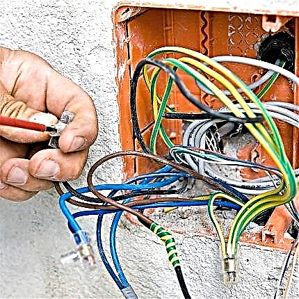
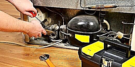
A multimeter is a portable device that helps to timely detect a break in the wiring, to monitor the operability of the heater and other electrical components in the circuit
Using a multimeter, you can check the voltage on any part of the circuit, in the connection of machines, sockets, and also check the battery charge
For household use, it is not necessary to buy an option with an expanded list of functions. A multimeter is enough to ring the circuit, measure the resistance and check the voltage
All multimeters on sale are divided into analog (with arrow indication) and digital (electronic options)
Digital multimeters are preferred by professional electricians, who need to record surges in the mains. It is easier and more convenient for independent masters to work with digital testers
During any operation to control and measure the readings of the power supply, battery power is consumed. All captured data is considered reliable until the battery is depleted.
One of the decisive characteristics of the testing device is the error. For household purposes, multimeters with an accuracy of up to 3% are suitable
A significant characteristic of a multimeter is considered to be the electrical safety class. CAT III multimeters are suitable for monitoring outdoor wiring, CAT II testers are used to check household electrical circuits inside an apartment / house, CAT I devices are used in monitoring low-voltage networks
Using a multimeter to solve everyday problems
Checking the voltage and other network characteristics with a multimeter
Range of possibilities of the control device
Pointer or analog test device
External differences between analog and digital devices
The accuracy of the digital instrument
Marginal error of control devices
Multimeter Electrical Safety Class
Metric devices come in two main types: analog and digital. These devices differ in functionality, measurement accuracy, build quality, and equipment. In any case, these are very useful measuring systems for everyone.
In the analogue multitester, the measurement result is displayed using the usual arrow on the scale. Sometimes the operation of such an analog device is not entirely appropriate - it is difficult for a beginner or non-specialist in the field of electrical engineering to deal with all scales, the “division price” of a certain parameter, and calculate the final value of the electrical characteristic.
And yet, the analog tester does not have a fixed arrow on the position, which makes it difficult to read the result and generally work with the device.
A digital multimeter presents measurement results as digital values on a liquid crystal screen. It provides utmost ease of use of the device, eliminates any errors associated with taking readings and calculating the required parameter, given the “division price” of the scale. This is one of the main reasons for the popularity of digital multi-testers among masters.
Image Gallery
Photo from
The control device made in the form of a pencil is more convenient in work
In addition to the usual probe, there is also a crocodile probe
For measurements, one of the probes extends from the device itself, the second is connected by a wire
Performing tests using a probe with a crocodile clip is much more convenient than using a device with two conventional probes. Especially if measurements need to be made
To power the device, standard finger batteries are used, which should be changed periodically
A significant minus of the device is the inability to measure the current strength. For those who need this feature, the device will not work.
On the other hand, the voltage in the power supply network produces a multitester pencil without direct contact, which is often necessary to check for hidden wiring
In addition to displaying test results on the display, the device sounds a sound about damage
Pencil Multi-Tester
Multimeter Pencil
Pencil voltage measurement
Using a crocodile clip
Battery powered instrument
Less device in the form of a pencil
Contactless definition
Sound signal
Standard multimeters can cost more than 5 cu But one thing always remains unchanged - the central place on the panel is occupied by a rotary trigger. The location of the remaining controls at the corners of the panel does not change, the presence of the necessary connectors at the bottom of the panel, multi-colored legend.
If you will purchase such a product, be sure to buy it with an external silicone case that protects from dust, moisture, drops from a small height, has special clips and a stand, which is very useful in the most unexpected situations of multitester operation.
Image Gallery
Photo from
The simplest version of the multitester
Conclusion of the taken indications on the display
Electromagnetic radiation
Household power supply
Given the topic and specifics of the article, we are talking about the metric measurement of a household power network. But to carry out work on determining the parameter values, it is necessary to have at least an approximate idea of the characteristics of the household electrical power network.
And the socket, in this case, acts exclusively as the “outlet point” of the voltage, so it is reasonable to know what voltage the consumer will “operate” with the socket.
Around the world, there are several main categories of electrical power networks for household appliances, one of which is “ours” 220 V at a frequency of 50 Hz. It represents two wires ("phase" and "zero"), the voltage between which is 220 V.
Recently, for supply systems for private houses and apartments, a 3-phase 380 V voltage network with a frequency of 50 Hz is sometimes connected to “power” such devices as a pumping station, compressor, lathe, etc.

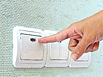
The household electric network “gives out” 220 V sockets (one phase) for current domestic appliances of foreign and domestic production: from kettles and hair dryers to dishwashers and washing machines
A logical question arises: why is it necessary to measure the characteristics of the network? On the one hand, the answer is obvious: if you do not know or are not confident in your beliefs about the outlet that you see in front of you and you need to do some work with wiring.
On the other hand, most electrical appliances are precisely designed for a specific frequency and voltage. Some electrical devices are designed to operate on a power source with a frequency of 60 Hz.
For example, the imported microwave oven manufactured in South Korea is equipped with a transformer, which can easily “swell” from “our” 50 Hz and it (the oven) will quickly fail.
Exceeding or decreasing the frequency, voltage and current strength can significantly change the efficiency of the devices, as a result, the electrical device breaks them down and subsequent operation is impossible. Multimeters are needed to measure and control such network parameters.
Safety measures before work
A multitester is a multifunctional portable device that is powered by a battery (usually a “crown”) and is a convenient, and most importantly safe, tool for the end user. But for its operation, there are certain rules of use.

“Krona” is a battery of galvanic batteries, overall dimensions are 48.5X26.5X17.5 mm. Battery weight is about 53-55 grams. The output voltage is 9 V, the average capacity is 600 mA * h
The tester itself is equipped with internal protection against overloads and overvoltages. But without following the rules below, it can also easily “burn out”, partially fail. To avoid this, there are a number of general rules for the safe operation of a digital tester.
When measuring the input AC voltage:
- If the preliminary value of the measured voltage is not determined, put the switch in the largest range.
- Do not apply voltages greater than 750 V to the input to avoid damage to the internal circuit.
Do not touch electrical components with your hands without dielectric gloves.
When measuring input DC and AC current:
- If the preliminary value of the measured current is not determined, put the switch in the largest range.
- If “1” is set on the LCD, set the trigger to the next range to increase the maximum value.
- When working with the “20A” connector, the test time should not exceed 15 seconds, since there is no fuse for this mode.
When measuring the internal resistance of the circuit, you need to make sure that the circuit power is off and all capacitors are discharged to “zero”.

The fuse is a glass flask with external metal contacts in the form of “caps”. Inside the bulb there is a piece of wire that melts at the moment of overload, it opens the circuit and keeps the device from breaking
In addition, there are special rules for the care and storage of the device, namely, it is not necessary to apply voltage to the input if the rotary switch is in the Ohm position, to work with the device if the housing cover is not completely closed. Lastly, the replacement of the galvanic battery and the fuse is carried out only when the device is turned off and the probes are disconnected.
Multimeter Symbols
In fact, a multi-tester consists of several standard parts: a display (in analog - a scale with a protective glass), a multi-position rotary switch, connectors for connecting probes. In this article, as a multimeter, the model DT9205A is considered.

The digital multitester DT9205A has wide capabilities, including AC and DC voltage and current measurement, resistance, capacitance, and diode health. Size - 186x86x41 mm, weight - 318 grams
Buttons:
- ON / OFF - turn on / off the device;
- HOLD - Holds the displayed value on the LCD screen.
Central Switch Sectors:
- hFE - measurement of transistor parameters;
- F, Ω- capacitor capacitance testing and resistance;
- A-, A ~ - direct and alternating current;
- V-, V ~ - direct and alternating voltage.
Main connectors:
- 20A - socket for measuring current strength up to 20A, red probe;
- A - socket for testing current strength within ranges;
- COM - socket for all modes, usually connect a black probe;
- VΩ - socket for measuring resistances and voltages.
The “pnp / npn” section connectors are semiconductor testing, the “cx” sections are connectors for inserting the tested capacitor. It is imperative to observe the polarity otherwise it will “swell”.

In order to correctly use the multi-tester, you should know what functions it is endowed with. The buttons with the designation of functions are located on the front panel (+)
Connecting probes to a multimeter
Test leads are a special type of connector that helps measure the characteristics of electrical parts and sections of a wire circuit. They easily connect the necessary connectors of the multitester with other outputs.
Usually they are a metal rod and plastic insulation, on one end of which the rod exit from the other is a wire with a connector for insertion into the connectors 20A, A, COM and VΩ of the device.
In addition, sometimes in the arsenal it is necessary to have an additional set of probes, but instead of the rod metal “crocodiles” are used - toothed clamps.

“Crocodile” is a special type of nozzles for multitester probes, very convenient when measuring electrical characteristics of medium and large parts
Most devices are imported from China, where they are manufactured in factories, workshops and mini-workshops. In this regard, manufacturers save on everything, including materials for the probes, which quickly fail.
It is recommended to make the probes yourself by buying parts on the radio market or in the radio store. Instead of insulating plastic, empty ampoules and shells for ballpoint pens are often used.

The COM connector is an electrical “minus", performs the function of grounding in all modes and ranges. Usually connect a black probe here
We connect the plug of the black probe to the multimeter connector with the symbol COM. And the plug of the red probe is connected to the connector with the designation VΩ, which is designed to measure direct and alternating voltage.
We strongly do not recommend clamping the red and black probes to a contact in any mode, with the exception of the rotary switch at the “►” position (chain ringing).

In addition to voltage, a multitester can measure the magnitude of the current and the value of resistance. It is important to remember that when measuring the resistance value, it is necessary to turn off the power
AC voltage measurement
Introductory and preparatory work done. We proceed to the actual completion of the assignment. First of all, turn off the multitester, if it is turned on. Press the ON / OFF button.
We translate the rotary trigger of the multimeter to the “750” position (in other testers there may be 600, 1000) of the “V ~” section. This means that the device can measure AC voltage parameters between 0 and 750 V.

If we set the range below the rated voltage sought (less than 200 V), we can disable the device, thereby creating a voltage situation. In the best case, you have to change the fuse, in the worst - “put” the multitester for parts
We turn on the tester, at least one “zero” should appear on the LCD screen - the device is ready for operation. We put the probes into the holes of the outlet in turn, it does not matter which where. We take readings of alternating current of a household power supply network.

The values on the screen jump and do not show exactly 220V - this is normal, because we are dealing with a single-phase network with alternating voltage
Work on testing the power supply network must be carried out quite accurately, slowly and without touching the exposed parts of the probes.
Outlet current measurement
Never, under any circumstances, measure the AC power of an outlet with a multitester directly, without a connected load. If you just put two probes from the tester into the outlet, you can “say goodbye” to the device. As a result, we get the “New Year's fireworks” and a burnt out electrical measuring device.
The current strength in a conventional outlet is necessarily measured with a series-connected load in the “tester-outlet” circuit. As an elementary load, even an ordinary light bulb with a cartridge (the place where the lamp is screwed in) can act.

To correctly measure the current strength in the circuit, we switch the trigger to the maximum position of the “A ~” section, in the presented device this value is 20 Amps. We rearrange the red probe into the connector labeled “20A” (UNFUSED - mode without a fuse, FUSED - mode with a fuse)
By connecting the tester and the bulb in series, we insert one of the probes into a socket, and connect one wire from the bulb base to the other probe. The second wire of the bulb is inserted into the free hole of the outlet. Take the current value. It is not recommended to measure more than 15 seconds in time.
And yet, current is not recommended to be measured in the socket. This does not carry any meaning. A household power network has simply the maximum limit in Amperes that must be observed. The current strength always exists only in the presence of a load, where we measure the current.
Measuring battery voltage and current
Instead of measuring the current strength in the outlet, it is better to learn how to measure direct current and voltage in batteries, accumulators and power supplies. It is much more interesting and safer. In addition, everyone has enough of these electrical elements. They are usually found in things like cameras, phones, tablets, children's toys, etc.
Batteries and accumulators are easy to distinguish: they all have special inscriptions near the output contacts in the form of “+” and “-“ icons. Testing such elements is not nearly more difficult than the voltage or current in the outlet.
Image Gallery
Photo from
To measure voltage indicators, the positive probe is connected to the right jack
The negative probe of the testing device is connected to the central socket on the front panel
To measure the constant voltage of power supplies, the switch is installed in the corresponding segment. In addition, a measurement limit is set, for example, for a battery it is 2 v
To measure the voltage in the power supply, the operating limit of which is 18 v, the switch should be set to a position indicating 20 v
If during the measurement process the device demonstrates minus indicators, then the plus and minus are mixed up, therefore, the probes must be applied on the other side
In order to measure alternating voltage, the switch is transferred to the corresponding segment located on the right side of the device
In order not to burn the tester when taking AC readings, it is better to set the highest measurement limit
Measurements are carried out when the probes are immersed in the contact holes of the outlet, during normal operation of the network, the device will show 220 - 230 v
Connecting the positive probe of the multimeter
Connecting the negative probe of the device
Setting the DC voltage limit
Setting the measurement limits for the power supply
An example of incorrectly positioned probes before testing
AC voltage test switch
The subtleties of testing AC voltage
Standard AC voltage reading
It should be noted that these batteries are usually characterized by small values of voltage and current. To measure a constant voltage or current on a battery, it is necessary to switch the rotary trigger of the multi-tester to the corresponding section mode “V-” or “A-” which is more than the value indicated on the outer shell of the element.
Turn on the tester. The black probe (zero) is connected to “-“, and the red probe is combined with “+”. We remove the fixed constant value. In this way, you can measure the basic electrical parameters of the batteries, which will help determine their working condition.
The clip will clearly demonstrate the sequence of actions during the measurement in dynamics:
The article readily talks about how to measure the voltage and current in the socket to all friends and only those who are familiar with electrical points and electrical wiring. Using a multimeter will significantly reduce the likelihood of hazardous situations when installing and repairing wiring, replacing sockets and switches.
Want to provide some interesting information about using a multimeter? Have questions in the process of getting acquainted with the article? Please write comments in the block intended for feedback.